

It’s in the Pipeline — A Guide to Performing Pipeline Hydraulic Calculations
Process Engineers execute hydraulic calculations during basic and detailed engineering project phases to size a variety of equipment including pumps, control valves and piping including piping components. These calculations are essential to ensure optimal designs on equipment and piping sizes based on specific design criteria while taking all operating cases into consideration.
Basic steps in successfully executing hydraulic calculations
Required Process Information
To start off with a hydraulic calculation, some fluid (commodity) properties and other aspects need to be available and considered. These may include:
|
Type of fluid |
Fluid Temperature |
| Fluid Phase | Atmospheric pressure at the project location |
| Fluid Density | Process conditions at source (fluid levels at source, pressures etc) |
| Fluid Viscosity |
Destination (tie-in) conditions (pressures, heights) |
Engineering Interfacing
Close collaboration is required between the process, mechanical and piping engineering disciplines to ensure pumps and other inline equipment is sized correctly for optimal performance. Important considerations are the following:
- Routing of Piping (length, bends, and elevations)
- Tie-in details at destination
Preliminary pipe routings will usually be done during basic engineering and finalised during detailed engineering. Hydraulic calculations done will be firmed up during the detailed engineering phase using final piping routing information.
Design Criteria and Design Cases
Some specifications and limitations to consider when performing the calculations are as follows:
- Material of construction
- Piping schedule
- Allowable fluid velocities
- Allowable pressure drops
Software such as AFT Fathom (incompressible fluids) and AFT Arrow (compressible fluids) can be used to perform calculations. When performing calculations, consideration should be given to the different possible design cases. It is highly likely that more than one case will exist. Different design cases can include:
- Changes in fluid temperatures/densities
- Changes in source vessel/tank levels
- Different required flow rates
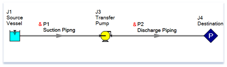
Figure 1: Example of a hydraulic model using AFT Fathom
Important Outputs
The aim of performing hydraulic calculations is to size the equipment and piping to develop datasheets, whilst adhering to the specifications, design criteria, piping routings and source and destination process conditions. The key outputs required may include:
- Pump NPSH available
- Pump motor size (hydraulic power)
- Pump duty point
- Line pressure drops and velocities
- Control Valve estimated CV value
Next Steps
Once all cases have been modelled datasheets for all equipment and instrumentation forming part of the piping system can be developed, which can then be sent into the market for quotations. Other deliverables that will be populated include process flow diagrams (PFDs), Piping and Instrumentation Diagrams (P&IDs), equipment list and the project line list amongst others.
~ Dewald Furter